Table of Contents
Tracing Options
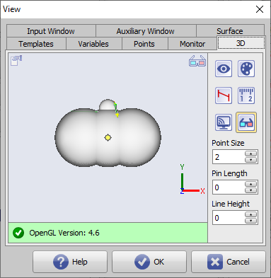
Using the [Options] button in the panel, you can make various settings on individual tabs with regard to graphics overlays on 2D and 3D image windows.
Tab |3D|
[Click on tab opens related wiki page]
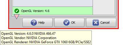
Status bar
The status bar in the 3D-View shows the suitability of the graphics card used for 3D rendering and the actuality of the installed OpenGL drivers. On MouseOver additional details are shown in the Hint.
Icon button [3D view]
The [3D View] icon button can be used to switch between 4 different graphics modes for displaying all 3D views at the local workstation provided that the graphics hardware and driver software used supports the selected display mode.

- Version 0: Slow / Color: Standard
- Version 1: Fast / Color: Standard
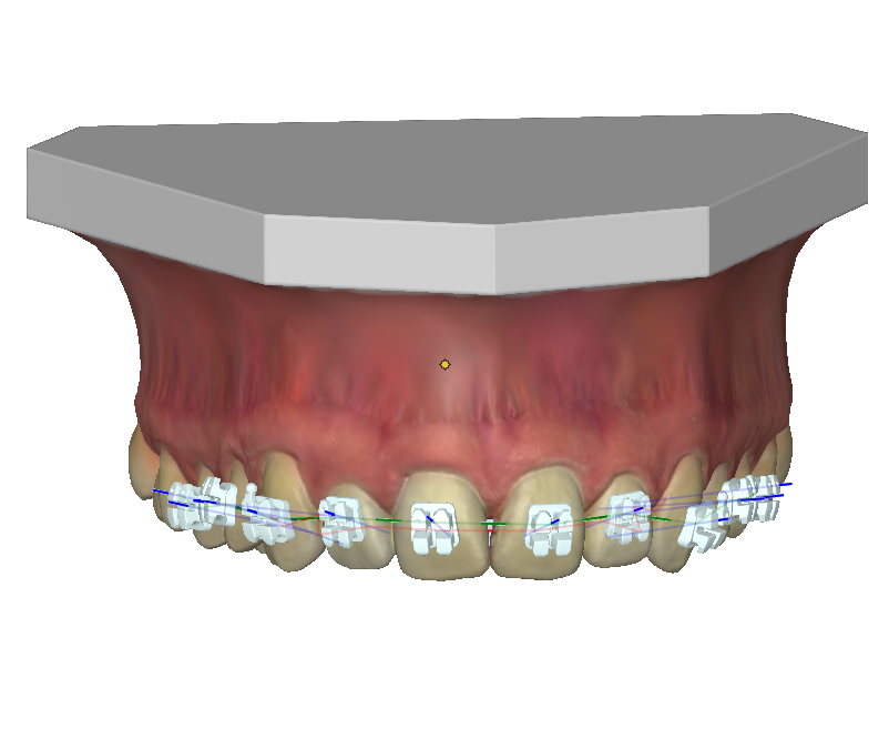
- Version 2: Fast / Color: Material
- Version 3: Fast / Color: Material + Shadow¹
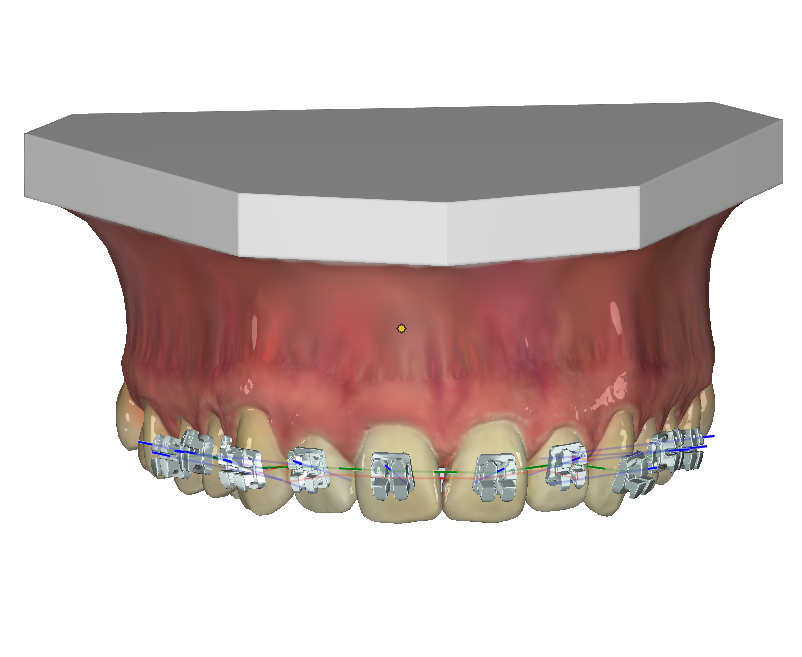
| Version 0 | Version 1 |
|---|---|
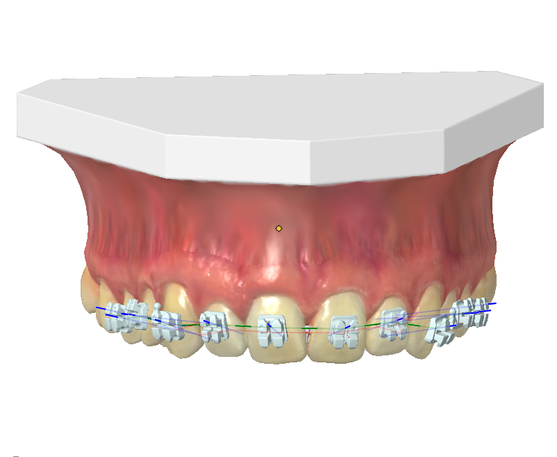 |  |
| Slow / Color: default | Fast / Color: default |
| Version 2 | Version 3 |
 | 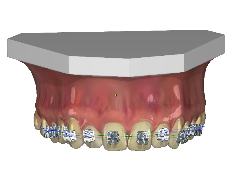 |
| Fast / Color: Material | Fast / Color: Material + Shadow |
¹ If possible the powerful Version 3 should be used. View properties like
- Highlights
- Brightness
- Blur
can be additionally adjusted in Panel View Options and also assigned module-specifically (system-wide for all workstations!).
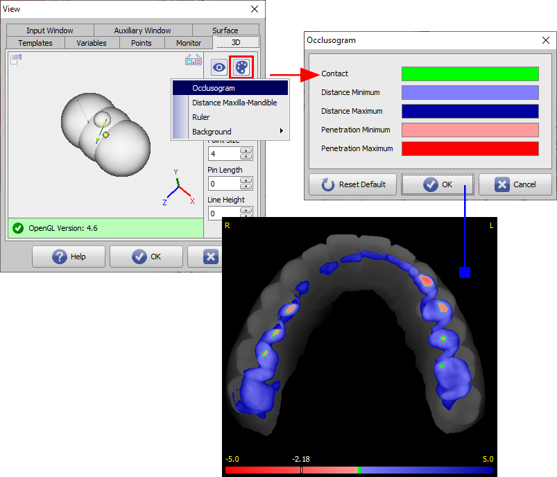
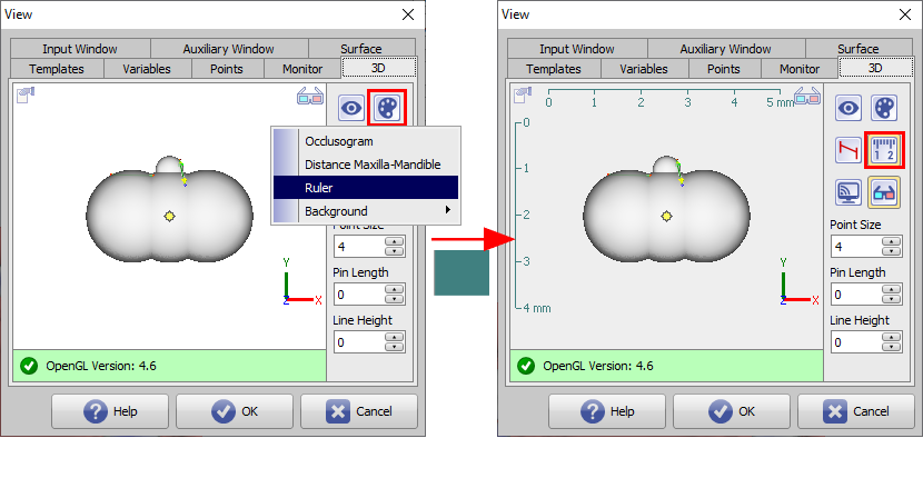
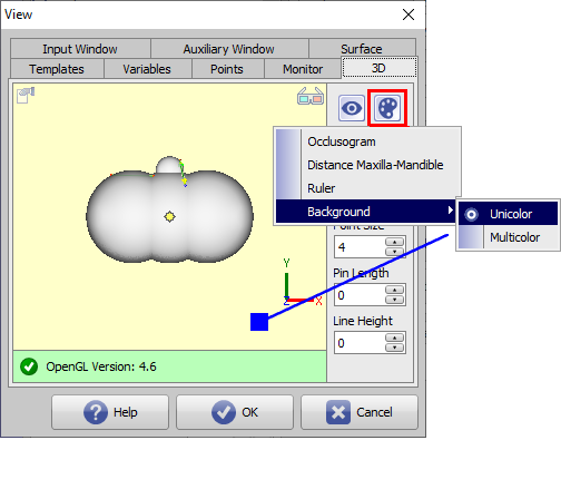
Icon button [Colors]
The [Colors] icon button can be used to make settings for

- Occlogram colors
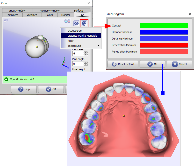
- Distance colors Maxilla - Mmandible
- Ruler color
- Background colors 3D view
- Unicolor
- Multicolor
• Occlogram colors
The colors used in the Occlusogram panel for occlusal crown distances can be set here. The default applies to all occlogram windows (all modules) in the workstation.
• Upper jaw-lower jaw spacing colors
The colors used on the segmented crown for occlusal crown spacing can be set here. The default applies to the Aligner 3D and V.T.O.3D modules at the workstation.
• Ruler color
Here you can set the color of the optional ruler displayed in the 3D-View. The default applies to the modules at the workstation.
• Background color 3D-View
Here you can set the background for 3D-Views. The default applies to all 3D views on the workspace except image preview on main window tab |images / 3D data| and full screen views.

Icon button [Lines perpendicular | Align Automatically]
The [Lines …] key can be used to specify whether measurement lines are to be drawn parallel to the object coordinate system or perpendicular to the respective reference plane.

Icon button [Show scale]
The [Ruler] button controls the display of a horizontal and vertical ruler in the ruler color set via [Colors] button within the 3D view. The setting is valid at the workstation and for all 3D views except for the full screen views.

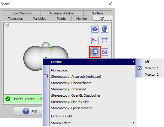
Icon button [View Mirror]
The [View] button determines whether the active 3D window should be displayed on a separate monitor in full screen and which display mode should be used for this (if supported by the hardware):
- Monoskopic
- Stereoskopy: Anaglyph (Rot/Cyan)
- Stereoskopy: Checkerboard
- Stereoskopy: Interlaced
- Stereoskopy: OpenGL Quadpuffer
- Stereoskopy: Side-by-Side
- Stereoskopy: Epson Moverio
In addition, when a stereoscopic display is selected, the stereo effect can be adjusted using a slider or reset to default.
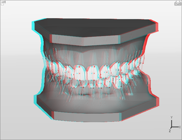
Icon button [Stereoskopy]
The [Stereoscopy] key is used to set which display mode is to be used for the active 3D window (if supported by the hardware):
- Monoskopic
- Stereoskopy: Anaglyph (Rot/Cyan)
- Stereoskopy: Checkerboard
- Stereoskopy: Interlaced
- Stereoskopy: OpenGL Quadpuffer
In addition, when a stereoscopic display is selected, the stereo effect can be adjusted using a slider or reset to default.

Note:
The selected stereo mode is activated and deactivated in the 3D-View via the stereo icon displayed at the top right.
| Stereomode inaktive | Stereomode aktive |
|---|---|
 |  |
Additional settings
In addition, on tab |3D| settings can be made for
- Point Size
- Pin Length
- Line Height
• Point Size
Parameter [Point size] controls the radius of the measuring point displayed as a 3D sphere in the 3D view between 1 and 40.
• Pin Length
Parameter [Pin length] controls the distance of a measuring point displayed as a 3D sphere from its position on the respective surface between 0 and 40.
• Line Height
Parameter [Line height] controls the spacing of dimensions between 0 and 40.
 | 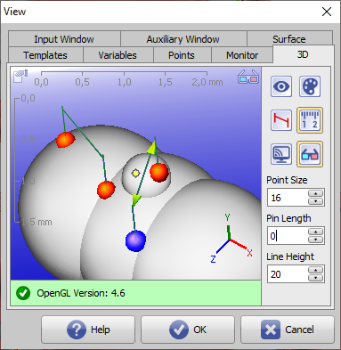 |
| (PS/PL/LH) = (1,0,0) | (PS/PL/LH) = (16,0,20) |
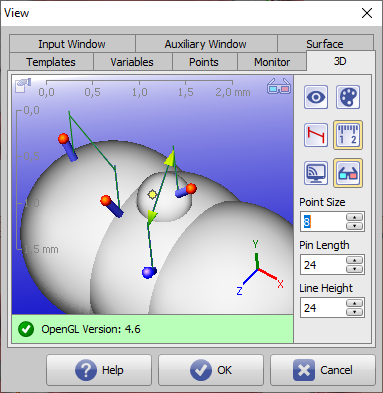 | 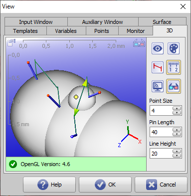 |
| (PS/PL/LH) = (8,24,24) | (PS/PL/LH) = (4,40,20) |